Views: 0 Author: Site Editor Publish Time: 2026-08-31 Origin: Site
As fleet electrification and public charging hubs scale into the megawatt range, traditional site design models break down under the weight of spatial, thermal, and grid constraints. Developers of any large EV charging project face a critical architectural bottleneck: deploying dozens of standalone chargers leads to stranded power capacity, excessive trenching costs, and inefficient land use. Resolving these inefficiencies requires a fundamental choice in hardware architecture at the design phase. This guide evaluates the technical and operational trade-offs between deploying a centralized split system versus traditional all-in-one units. You will learn how to optimize site layout, manage dynamic power sharing, and future-proof infrastructure for heavy-duty vehicle demands. Choosing the correct hardware configuration directly dictates site throughput, utility interconnection timelines, and long-term operational viability.
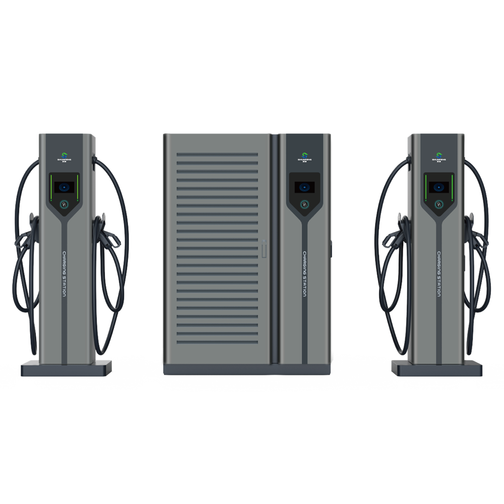
Spatial Efficiency: Charging stacks separate the power cabinet from the user interface, allowing for ultra-slim dispensers at the parking bay, whereas integrated DC chargers require a larger footprint per stall.
Dynamic Power Allocation & The 80% Rule: An EV charging stack system inherently supports dynamic load sharing across multiple dispensers, capitalizing on the natural drop in EV power draw after 80% State of Charge (SoC) to minimize stranded capacity.
Installation Economics & Deployment Speed: Integrated chargers offer simpler, faster deployment for smaller sites, but charging stacks drastically reduce trenching, heavy AC cabling costs, and grid upgrades at scale.
Maintenance Realities: Centralized stacks consolidate power modules and spare parts inventory for easier maintenance but introduce a localized point of failure; integrated units isolate failures but require servicing complex active cooling and conversion components across the entire site footprint.
The split architecture fundamentally redesigns how power moves from the grid to the vehicle. Heavy AC-to-DC power conversion happens inside centralized cabinets located away from the primary parking stalls. These cabinets house multiple independent power modules. They connect via underground DC cables to slim, user-facing dispensers positioned directly at the parking bays. This separation isolates the heavy, noisy, and heat-generating components from the driver. Field installations typically place the main power cabinets near the utility switchgear, minimizing the length of expensive, large-gauge AC wire runs.
A modern EV charging stack system relies on a highly modular internal design. The central cabinet contains interchangeable power blocks, typically rated between 30kW and 50kW each. A central control matrix dynamically routes the output of these blocks to whichever dispenser requires power. If a power module fails, technicians can swap it out without taking the entire system offline. This modularity provides significant flexibility for site operators managing varying vehicle types and charge states. The dispensers themselves contain minimal active components, primarily housing the charging cable, a basic user interface, and contactors.
The all-in-one architecture represents the traditional approach to fast charging. AC-to-DC conversion, control systems, active cooling fans, and dispensing cables all exist within a single physical enclosure. You install this unit directly at the parking stall. The utility grid feeds high-voltage AC power straight to the unit, and the internal rectifiers handle the conversion just inches away from the vehicle port. This requires running heavy AC conduit across the entire parking lot to reach every individual stall.
This standard operational model typically serves one to two vehicles simultaneously. Power capacities remain locked to the physical unit. If you install a 150kW integrated DC charger, that specific parking stall has a hard limit of 150kW. The internal components are tightly packed, requiring complex liquid or forced-air cooling systems to manage the immense heat generated during the conversion process. This dense packaging makes the physical footprint of the unit quite large. Site preparation requires pouring substantial concrete pads, often reinforced with rebar, and installing heavy-duty steel bollards to protect the equipment from vehicle strikes.
Physical space remains one of the strictest constraints in civil engineering. Evaluating the available footprint requires analyzing vehicle turning radii, parking stall dimensions, and pedestrian walkways. Heavy-duty transit vehicles require massive clearance to navigate safely. Placing bulky equipment directly on the parking island restricts driver visibility and increases the risk of collision. When laying out a depot, every square foot dedicated to hardware is a square foot taken away from vehicle maneuverability.
Strict accessibility requirements further complicate site design. Wheelchair access mandates clear pathways around the dispensing equipment. Heavy liquid-cooled cables must remain manageable for all users. Slim dispensers make it significantly easier to meet these accessibility standards. They leave ample room for wheelchair ramps and require less physical effort to maneuver the charging connector into the vehicle port. Meeting ADA reach ranges is far simpler when the dispenser profile is narrow and the heavy power electronics are located elsewhere on the property.
Determining the maximum available utility power dictates the entire scope of the installation. Utility transformers have strict limits. Exceeding these limits requires time-consuming infrastructure upgrades, often involving months of lead time for new switchgear and utility-side transformers. Site developers must carefully calculate the aggregate draw of all planned hardware to ensure it aligns with the local grid capacity. You cannot simply assume the utility will provide unlimited power to your property line.
Managing ongoing demand charges is equally critical. Utilities penalize commercial sites for high peak power consumption. Implementing peak shaving strategies helps flatten the load profile. Hardware that allows precise control over power output enables operators to keep their total site draw below punitive utility thresholds. Efficient power routing prevents unnecessary spikes in demand, ensuring the site operates within its engineered electrical limits without tripping main breakers or incurring massive utility penalties.
Matching hardware output capabilities to specific operational schedules ensures vehicles return to service on time. Overnight transit buses have long dwell times, allowing for slower, sustained power delivery. Rapid-turnaround logistics fleets require massive bursts of energy in very short windows. The hardware architecture must align perfectly with these distinct operational profiles. Installing high-output chargers for vehicles that sit idle for twelve hours represents a massive misallocation of site resources.
Site operators must account for the natural behavior of lithium-ion batteries. The "80% rule" dictates that charge acceptance tapers off significantly once the battery reaches 80% State of Charge. Pushing maximum power into a nearly full battery causes overheating and degradation. Therefore, a vehicle plugged into a high-output charger will only draw a fraction of the available power during the final 20% of its charging session. Hardware selection must account for this taper to avoid stranding power capacity at stalls where vehicles are simply topping off.
Integrated units demand substantial real estate at every single parking spot. Field installations typically require pouring a dedicated concrete pad measuring at least four feet by four feet, reinforced with rebar to support equipment weighing upwards of a thousand pounds. You must install steel bollards around each unit to provide crash protection from heavy-duty vehicles. This infrastructure eats into the available parking area, often forcing developers to reduce the total number of active stalls. The sheer size of the units can obstruct driver sightlines, creating safety hazards in busy depots where large trucks are constantly maneuvering.
Centralized architectures move the bulk of the heavy hardware to a low-value area of the site, such as a perimeter wall or an unused corner near the main electrical service. This allows for high-density parking arrangements. The slim dispensers require minimal concrete work and integrate easily into existing parking islands. This layout facilitates safer traffic flow and simplifies compliance with strict aisle width requirements. You can fit more active charging stalls into a smaller physical footprint when the power conversion hardware is removed from the immediate parking area.
Power allocation represents the most significant operational difference between the two systems. Integrated units generally feature locked power capacities. If a vehicle requests 50kW from a 150kW charger, the remaining 100kW sits completely unused. As the vehicle reaches 80% SoC and tapers its draw, even more capacity becomes stranded. Other vehicles on the site cannot access this unused power. This static allocation forces developers to overbuild their grid connection to ensure every stall has maximum power available, even though vehicles rarely draw maximum power simultaneously.
A centralized high power charging system eliminates this inefficiency through dynamic routing. The central matrix constantly monitors the exact power demand of every connected vehicle. If one vehicle tapers its charge, the system automatically redirects the freed-up power modules to a newly arrived vehicle with a depleted battery. This dynamic load management maximizes total site utilization and ensures no power goes to waste. You can install more dispensers than your total grid capacity would normally allow, relying on the software to distribute power intelligently based on real-time vehicle demand.
Integrated hardware often presents a lower upfront hardware cost per unit. The plug-and-play nature of these chargers allows for faster deployment on tight project timelines. However, site-wide installation costs scale poorly. Running heavy, high-voltage AC lines from the main switchgear to every single parking stall requires massive copper conductors and extensive trenching. You must dig deep trenches across the entire parking lot, lay Schedule 80 PVC conduit, and pull thick, difficult-to-manage wire to every single stall. These civil engineering costs quickly outpace the savings on the hardware itself.
Split systems require a higher initial capital expenditure for the centralized power cabinet. The upfront civil engineering around the main equipment pad is more complex, requiring larger concrete pours and heavier lifting equipment. Yet, installation costs drop significantly at scale. You only run one massive AC feed to the central cabinet. From there, you run lighter, less expensive DC conduit to the individual dispensers. Consolidating the AC trenching drastically reduces the overall civil construction budget. Pulling DC cables to the dispensers is faster and requires less labor than pulling heavy AC feeds to dozens of individual integrated units.
The isolated architecture of an integrated commercial DC charger offers high site-wide redundancy. If one unit suffers a catastrophic failure, it only affects the one or two stalls directly connected to it. The rest of the site continues operating normally. However, ongoing O&M costs remain high. Technicians must service complex active cooling systems, replace air filters, and troubleshoot power electronics across a wide physical footprint. Performing preventative maintenance requires walking the entire site, opening dozens of individual cabinets, and checking hundreds of individual cooling fans.
Centralized systems consolidate maintenance efforts. Technicians perform the majority of their work at one central cabinet, protected from traffic and weather. The standardized power modules streamline spare parts inventory. You only need to stock one type of module rather than entirely different charger models. The primary drawback is the risk of a centralized failure. A catastrophic issue at the main cabinet can take multiple dispensers offline simultaneously. Site operators must weigh the convenience of centralized maintenance against the potential impact of a localized hardware failure.
Feature | Integrated DC Charger | Charging Stack (Split System) |
|---|---|---|
Footprint per Stall | Large (requires heavy pads & bollards) | Minimal (slim dispensers only) |
Power Allocation | Static / Locked to the unit | Dynamic / Shared across dispensers |
Stranded Capacity | High (especially after 80% SoC) | Low (power routes to other vehicles) |
Installation at Scale | Expensive (heavy AC trenching everywhere) | Efficient (consolidated AC, lighter DC runs) |
Maintenance Location | Dispersed across all parking stalls | Centralized at the main power cabinet |
Scaling infrastructure to meet growing fleet demands requires careful planning. Split systems offer a distinct advantage here. Expanding capacity often involves simply adding internal power modules to an existing charging stack. If the initial installation included a 360kW cabinet populated with only 180kW of modules, operators can double the site output later without breaking ground. You slide new modules into the empty slots, update the firmware, and instantly increase the power available to the dispensers. This prevents the need for trenching new lines, pulling new wire, or adding new physical footprints to the parking lot. The underground infrastructure remains completely untouched during the upgrade process.
The automotive industry is rapidly transitioning from legacy 400V architectures to modern 800V systems. Higher voltages allow for faster charging times and lighter vehicle wiring harnesses. Centralized systems are uniquely positioned to support this transition. The dynamic routing matrix can allocate voltage and amperage precisely based on the specific vehicle plugged in. The system can deliver 400V to a legacy delivery van and instantly switch to 800V for a newly acquired heavy-duty transit bus. This adaptability ensures the hardware remains relevant as fleet compositions evolve. You do not need to segregate your parking lot into 400V and 800V charging zones.
Upgrading all-in-one units presents a much harsher reality. When fleet battery capacities increase and higher kilowatt outputs become necessary, operators often face a complete replacement scenario. You cannot easily add 50kW of capacity to a locked 100kW integrated unit. The entire machine must be unbolted, removed, and replaced with a larger model. This requires new concrete work, potentially larger AC conduit runs to handle the increased amperage, and significant downtime for the affected parking stalls. The lack of modularity severely limits long-term flexibility and forces operators into expensive hardware replacement cycles.
Moving power over long distances generates heat and causes voltage drop. Long DC cable runs from a central cabinet to distant dispensers require careful engineering. Excessive heat degrades cable insulation and reduces overall system efficiency. To mitigate this risk, developers must strictly adhere to manufacturer distance limits between the stack and the dispenser. For applications exceeding 350 amps, utilizing advanced liquid-cooled cables becomes mandatory. These cables circulate a glycol mixture to manage temperatures, ensuring safe and efficient power delivery even during peak output sessions. Proper conduit sizing and thermal derating calculations are non-negotiable during the design phase.
Centralizing power conversion introduces a single point of failure. If the main grid feed to the cabinet drops, or the central routing matrix fails, every connected dispenser goes offline. This halts fleet operations entirely. Mitigating this risk requires intelligent site design. Instead of relying on one massive 720kW cabinet, developers should install multiple, overlapping systems. Deploying two independent 360kW cabinets ensures N+1 redundancy. If one cabinet requires maintenance, the other continues powering half the site, maintaining partial uptime and keeping vehicles moving. Cross-wiring dispensers to alternate cabinets further isolates potential failures.
High-capacity centralized systems draw massive amounts of power, often triggering lengthy utility transformer upgrades. Utilities can take months or even years to procure and install the necessary switchgear. To expedite deployment, developers can pair the hardware with Battery Energy Storage Systems (BESS). The batteries buffer the grid draw, allowing the site to operate on a smaller utility connection. The BESS charges slowly overnight and discharges rapidly during peak charging sessions. This manages peak loads, avoids demand charges, and significantly accelerates utility approvals by reducing the immediate strain on the local distribution grid.
Centralized architectures excel in environments where space is tight and utilization is high. High-density fleet depots benefit immensely from slim dispensers that do not impede vehicle movement. Space-constrained urban charging hubs require the highest possible power density per square foot. Any project requiring dynamic power sharing across more than six stalls should utilize a split system. The ability to combat the 80% charge curve drop-off ensures that every kilowatt of grid capacity actively contributes to charging vehicles, maximizing throughput and operational efficiency. If your site features vehicles with varying battery sizes and unpredictable arrival times, dynamic routing is mandatory.
All-in-one units remain the standard for specific deployment scenarios. Highway corridor charging locations often feature dispersed parking layouts where trenching distances make centralized systems impractical. Retail locations adding a few chargers as an amenity benefit from the plug-and-play simplicity. For smaller deployments under four to six stalls, the rapid deployment speed and lower upfront hardware costs make integrated units the logical choice. In these scenarios, the isolated redundancy outweighs the benefits of dynamic power routing. If you are only installing two chargers in a massive parking lot, running long DC cables from a central cabinet makes no engineering sense.
Audit your site's utility interconnection limits and available square footage for centralized power cabinets.
Perform a fleet dwell-time analysis to identify how many vehicles will hit the 80% charge curve simultaneously.
Calculate exact trenching distances between the proposed main switchgear and the furthest parking stall.
Consult your local utility provider regarding peak demand charges and battery storage integration feasibility.
A: A split system separates the heavy AC-to-DC power conversion into a central cabinet, sending DC power to slim dispensers at the parking stall. An integrated unit houses all conversion, cooling, and dispensing components within a single, larger enclosure directly at the parking space.
A: It uses dynamic load sharing via a central routing matrix. When a vehicle reaches 80% SoC and its power demand drops, the system automatically redirects the unused power modules to another vehicle with a lower battery level, ensuring maximum site utilization.
A: Integrated units are cheaper and faster to deploy for small sites with only a few stalls. However, for large projects, split systems drastically reduce installation costs by minimizing the need for heavy AC cabling and extensive trenching across the entire parking lot.
A: Standard industry ranges typically fall between 30 to 100 meters. Exceeding these limits introduces severe voltage drop and requires complex thermal management, often necessitating advanced liquid-cooled cables to maintain safe operation.
A: Yes. Operators can add modular power blocks directly into the centralized cabinet to increase the total kilowatt output. This supports the transition to 800V architectures while keeping the existing underground conduit and user-facing dispensers completely intact.