


Views: 0 Author: Site Editor Publish Time: 2026-08-01 Origin: Site


A common industry misconception assumes the visible dispenser on the forecourt is the sole determinant of fueling speed and performance. Operators often overlook the critical infrastructure beneath the surface, believing any dispenser can simply be bolted onto any storage tank. This fundamental misunderstanding ignores the complex hydraulic relationship between the storage vessel and the metering equipment above ground. Mismatching pumping mechanisms with fuel storage capacities leads directly to flow rate bottlenecks, premature mechanical wear, cavitation issues, and increased maintenance demands. When the suction lift or pressure requirements of a specific tank volume do not align with the chosen pumping hardware, the entire fueling operation suffers. Customers experience slow fill times, while the hardware itself degrades rapidly under improper hydraulic loads. Aligning underground storage tank (UST) or aboveground storage tank (AST) volume with the correct pumping architecture is essential. From high-volume submersible turbines designed for massive underground reserves to specialized mobile setups for temporary sites, matching the hardware to the storage capacity ensures operational efficiency, maintains consistent flow rates, and guarantees regulatory compliance.
Pump Architecture Varies by Storage: High-capacity underground tanks rely on Submersible Turbine Pumps (STPs) located inside the tank, whereas smaller or aboveground tanks often utilize suction pumps housed within the dispenser itself.
Throughput Dictates Hardware: A site’s peak flow requirements determine whether a standard single-hose unit or a high-volume 4 nozzle fuel dispenser is required, which in turn dictates the necessary line pressure and storage capacity.
Blending Reduces Tank Requirements: Modern dispensers utilize proportional blending valves, allowing sites to offer multiple fuel grades (e.g., mid-grade) from just two primary storage tanks (regular and premium), optimizing storage capacity.
Specialty Fuels Require Isolation: Specialty fuels like E85, E0, and diesel require completely isolated hydraulic lines and specialized materials within the fuel dispenser pump to prevent cross-contamination and chemical degradation.
Mobility Requires Specialized Pumping: Temporary or low-volume sites require a dedicated mobile fuel station pump system engineered to handle the specific pressure and safety constraints of portable skid tanks.
Understanding the technical distinction between a fuel dispenser pump and the actual pumping mechanism is the first step in site design. The dispenser is the user-facing metering, filtering, and hose unit. The actual pump is the mechanical device generating fluid flow, which may be located inside the dispenser cabinet or submerged deep within the storage tank. This distinction dictates how fuel moves from storage to the vehicle. Field technicians know that confusing these two components leads to disastrous site engineering. You cannot fix a flow rate issue at the nozzle if the underground turbine is undersized for the tank depth.
The physics of fuel transfer heavily depend on storage depth, piping distance, and tank volume. These factors impact head pressure and suction lift limitations. As fuel is drawn from a tank, the pump must overcome the vertical distance and the friction of the piping. Deeper tanks or longer piping runs require more mechanical force to move the fluid. Fluid dynamics dictate that every 90-degree elbow and every foot of horizontal pipe adds friction loss. This directly influences the type of pumping hardware required to maintain a steady flow at the nozzle. If you ignore pipe friction calculations, you will end up with a system that starves the dispenser during peak hours.
Tank structural constraints also play a significant role in hardware selection. Double-walled fiberglass and steel tank designs affect riser sizing, pump mounting load, and maximum allowable head pressure under peak flow conditions. Steel tanks may tolerate different vibration profiles compared to fiberglass, influencing where and how submersible pumps are mounted. These structural realities dictate the physical installation parameters for the pumping equipment. You must account for the dead weight of the pump motor hanging off the riser pipe. Fiberglass tanks require specific load-bearing collars to prevent structural cracking under the torque of a 2 HP motor kicking on.
Operators must recognize the capacity threshold where simple suction-based systems fail to perform adequately. When storage volumes increase and tanks are buried deeper, operators must transition to pressurized submersible systems. This transition is critical to maintain consistent flow rates and ensure the gas station pump capacity meets customer demand during peak hours without straining the mechanical components. A standard rule of thumb in the field is that anything buried deeper than 12 feet or requiring a horizontal run longer than 50 feet demands a pressurized system. Pushing fuel is always more efficient than pulling it.
Comparison of Pumping Architectures Based on Tank Capacity |
||||
Tank Capacity (Gallons) |
Typical Tank Type |
Recommended Pump Architecture |
Primary Advantage |
Primary Limitation |
|---|---|---|---|---|
Under 1,000 |
Skid / Mobile AST |
12V/24V DC Suction |
High portability and easy deployment |
Low flow rates (15-20 GPM max) |
1,000 - 5,000 |
Standard AST |
Internal Dispenser Suction |
Simplified maintenance above ground |
Strict suction lift limits (10-15 ft) |
5,000 - 10,000 |
Shallow UST / Large AST |
Fractional HP Submersible |
Consistent pressure over medium runs |
Struggles with simultaneous multi-dispenser use |
10,000+ |
Deep UST |
2 HP - 5 HP Submersible Turbine |
Pushes high volume to multiple islands |
Requires complex leak detection systems |
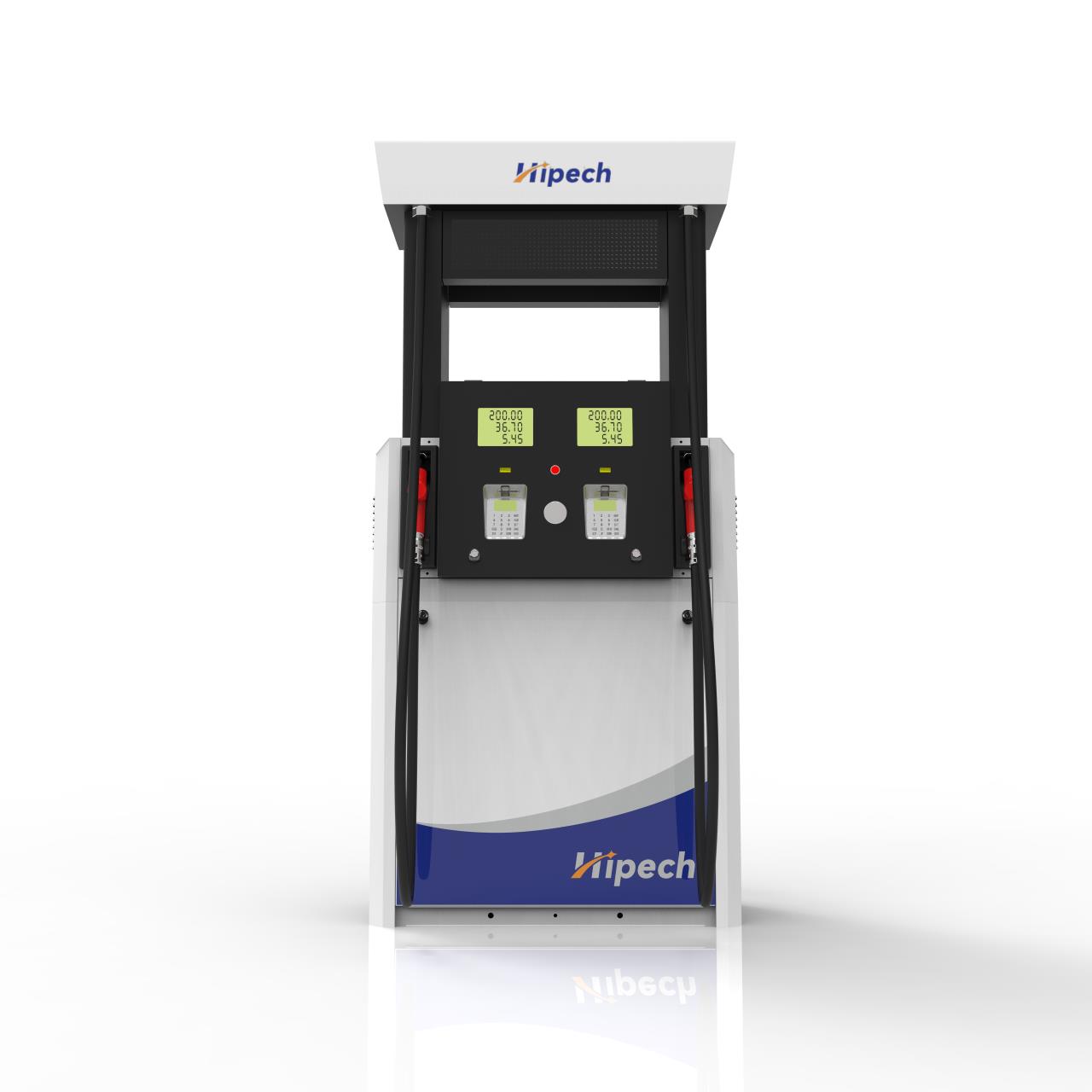
High-capacity underground storage tanks rely exclusively on Submersible Turbine Pumps (STPs). These powerful units sit at the bottom of large USTs, pushing fuel upward and outward to multiple dispensers simultaneously. By pressurizing the lines from the source, STPs eliminate the vapor lock and suction lift issues associated with drawing fuel from deep underground reserves. When you have a 20,000-gallon tank buried under a concrete forecourt, a suction pump inside the dispenser cabinet will simply pull a vacuum and cavitate. The STP uses a series of impellers to generate head pressure, forcing the liquid up the riser and into the primary product lines.
Physical underground piping loops connect a single dispenser to multiple large USTs to support diverse product offerings. This multi-product plumbing requires precise engineering to maintain pressure across the entire forecourt. When a customer selects a specific grade, the corresponding STP activates, pushing the fuel through the designated piping loop directly to the metering unit. The piping network must be sized correctly. Using 1.5-inch pipe for a high-volume site will create a bottleneck, regardless of how powerful the STP is. Upgrading to 2-inch or 3-inch fiberglass piping reduces friction and allows the pump to deliver its rated capacity.
When multiple high-capacity tanks hold the same product, they are often manifolded together. This requires advanced pump controllers to alternate STP operation, preventing uneven tank drawdown. Manifolding and redundancy ensure that if one STP fails, the site can continue operating using the secondary tank and pump, maintaining continuous service during high-demand periods. Syphon loops connect the tanks, allowing them to level out hydraulically. The pump controller monitors the fluid levels and alternates the lead pump, ensuring even wear on the motors and preventing one tank from running dry while the other remains full.
Pressurized lines originating from high-capacity tanks must include mechanical or electronic line leak detectors. These regulatory safety devices monitor line pressure when the STP is inactive. If a pressure drop is detected, indicating a potential leak, the system restricts flow to prevent environmental contamination, ensuring compliance with strict environmental regulations. Mechanical detectors use a spring-loaded piston that reacts to line pressure. If the line cannot hold 3 PSI, the piston restricts flow to 3 GPM, signaling to the operator that a leak is present. Electronic systems provide more precise monitoring, shutting down the turbine entirely if a leak is detected.
Sites utilizing 1,000 to 5,000-gallon ASTs frequently employ suction pump systems. In these configurations, the pumping mechanism is housed directly inside the dispenser cabinet. The pump creates a vacuum, drawing fuel out of the tank and into the metering unit. This setup is common for mid-sized commercial operations or fleet fueling where tanks are located relatively close to the dispensing area. Because the tank is above ground, the vertical lift is often minimal, making suction a viable and cost-effective option. Maintenance is also simplified, as the pump motor is easily accessible inside the dispenser doors rather than buried in a tank sump.
Suction systems face strict physical limitations, typically maxing out at 10 to 15 feet of vertical suction lift. If the tank is too deep or the piping run too long, the pump cannot overcome the atmospheric pressure and fluid friction, resulting in cavitation and flow failure. This physical reality restricts the distance and layout configurations between the storage tank and the dispensing hardware. Atmospheric pressure at sea level is roughly 14.7 PSI. A perfect vacuum can only lift water about 34 feet, and gasoline, being lighter, slightly more. However, pump inefficiencies and pipe friction mean practical lifts are much lower. If you try to pull fuel 20 feet vertically, the fuel will vaporize in the line before it reaches the pump.
Piping length, vertical rises, and elbows from ASTs severely impact suction lift calculations and overall flow performance. Every bend and foot of horizontal pipe adds friction loss. Engineers must carefully calculate these variables to ensure the suction pump can deliver the required flow rate without overworking the motor or causing premature mechanical failure. A common mistake is using too many 90-degree elbows to route piping around concrete footings. Each elbow adds the equivalent of several feet of straight pipe friction. Using 45-degree sweeps instead of hard 90s can significantly improve suction performance and extend the life of the pump vanes.
Pairing standard dispensers with mid-capacity ASTs requires strict adherence to fire code and venting requirements. Above-ground tanks are exposed to ambient temperature fluctuations, causing fuel expansion and vapor generation. Proper vapor recovery systems and pressure-relief venting are mandatory to prevent hazardous pressure buildup and ensure safe operation near the dispensing equipment. When the sun beats down on a steel AST, the fuel expands. If the emergency vent is undersized, the tank can rupture. Additionally, anti-siphon valves must be installed at the tank outlet to prevent the entire tank contents from draining onto the ground if the suction line breaks below the fluid level.
For agricultural use, construction sites, or skid tanks under 1,000 gallons, operators rely on a portable fuel dispenser pump. These units are designed for durability and ease of installation in non-traditional environments. They prioritize ruggedness over high-speed throughput, providing reliable fuel access where permanent infrastructure is impossible. You will often see these bolted directly to the top of a square steel skid tank on a logging site. They use heavy-duty cast iron housings and bypass valves designed to handle dirty fuel and rough handling. They are not meant to fill a car in two minutes; they are meant to survive being hit by a tractor.
Temporary sites often deploy a dedicated mobile fuel station pump system. These containerized or truck-mounted systems utilize 12V or 24V DC pumps, delivering lower flow rates around 15 to 20 GPM. Engineered with integrated filtration, they handle the specific pressure constraints and fuel quality challenges inherent in rugged, low-capacity remote environments. Running off a vehicle battery means you do not need a dedicated AC power drop. The integrated particulate and water filters are critical here, as fuel delivered to remote sites often contains condensation and rust. The pump must push through these dense filter media without stalling.
Assess the site location to determine if AC power is available or if DC battery power is required.
Calculate the required daily throughput to size the skid tank appropriately, ensuring you do not need daily fuel deliveries.
Install a high-capacity water-absorbing filter directly after the pump discharge to protect fleet vehicles from contaminated fuel.
Ensure the skid tank is properly grounded to a grounding rod to dissipate static electricity generated during the pumping process.
Modern gas stations typically offer three or four grades of gasoline from only two underground tanks containing Regular and Premium fuel. This is achieved using variable blending valves located inside the dispenser cabinet. By mixing the two base products in specific ratios, the site can offer mid-grade options without requiring a dedicated storage tank for every octane level. This is a massive cost saving in site construction. Burying a third 10,000-gallon tank costs tens of thousands of dollars in excavation, backfill, and piping. Blending allows you to achieve the same retail offering with a smaller underground footprint.
Proportional control valves precisely mix 87 octane regular and 91-94 octane premium at the nozzle. To achieve a mid-grade octane rating of 89 or 90, the dispenser's internal computer adjusts the valves to draw specific percentages from each tank simultaneously. This dynamic mixing occurs in real-time as the fuel flows into the vehicle. The blend ratio is controlled by a stepper motor that opens and closes the respective product valves based on feedback from the flow meters. If the regular line pressure drops slightly, the valve opens wider to compensate, ensuring the final octane rating remains legally compliant.
This blending technology drastically reduces the total number of required tanks on site. By eliminating the need for a dedicated mid-grade tank, operators optimize their underground footprint. This alters the required pumping capacity and simplifies the piping infrastructure, allowing for more efficient site design and reduced installation complexity. However, it means both the regular and premium STPs must run simultaneously when a customer selects mid-grade. The electrical panel must be sized to handle the starting current of multiple turbine motors kicking on at the exact same time.
Alternative fuels like E85, E0 (ethanol-free), and diesel cannot share blending manifolds with standard gasoline. These products must be physically isolated to prevent cross-contamination. Mixing diesel with gasoline, or introducing high-ethanol blends into standard vehicles, causes severe engine damage. Dedicated lines and separate metering units are mandatory for these specialty fuels. You cannot run diesel through a gasoline meter, as the viscosity difference will throw off the calibration. Furthermore, the flash points are different, requiring different safety setbacks and vapor recovery protocols.
Handling highly corrosive ethanol blends requires specialized material compatibility. The dispenser hydraulics must utilize specialized elastomers, nickel-plated components, and stainless steel. Standard aluminum or standard rubber seals will degrade rapidly when exposed to E85, leading to dangerous leaks and catastrophic equipment failure. Ethanol acts as a solvent. It will strip the plasticizers out of standard Buna-N O-rings, causing them to shrink and crack. When installing an E85 system, every single component from the tank sump to the nozzle swivel must be UL-listed specifically for high-ethanol blends.
Material Compatibility for Fuel Dispenser Components |
|||
Fuel Type |
Acceptable O-Ring Material |
Acceptable Piping Material |
Meter Construction |
|---|---|---|---|
Standard Gasoline (E10) |
Buna-N / Viton |
Fiberglass / Flexible Plastic |
Standard Aluminum |
Diesel / Biodiesel (B20) |
Viton / Teflon |
Fiberglass / Steel |
Treated Aluminum / Cast Iron |
E85 (85% Ethanol) |
Specialty Fluorocarbon |
Stainless Steel / Lined Flex |
Nickel-Plated / Stainless |
Aviation Fuel (Avgas) |
Viton |
Epoxy-Lined Steel / Stainless |
Stainless Steel |
Adding specialty fuel lines to an existing site presents significant retrofitting constraints. Operators cannot simply reassign an existing pipe to E85 without verifying material compatibility underground. Often, introducing a new specialty fuel requires breaking concrete to install new, chemically compatible piping and upgrading the internal components of the dispensing units. If you push E85 through an old fiberglass line not rated for it, the pipe will delaminate internally. The resin will dissolve, clogging the dispenser filters and eventually causing a massive underground leak. Retrofitting requires a complete audit of the existing underground infrastructure.
Commercial trucking facilities require specialized equipment like a 4 nozzle fuel dispenser configured in a master/satellite arrangement. This allows drivers to fuel dual saddle tanks simultaneously without moving the truck. These multi-hose dispensers are engineered for maximum throughput, minimizing downtime for commercial fleets. A standard retail pump delivers 10 GPM. A commercial truck with 300-gallon tanks would take 30 minutes to fill at that rate. High-volume commercial units push 40 to 60 GPM, getting the truck back on the road in under ten minutes.
Internal hydraulic blocks, dual meters, and mechanical interlocks are required to prevent cross-contamination and maintain constant pressure when multiple grades are dispensed at once. The internal plumbing of a high-volume unit is significantly more complex than a standard retail dispenser, ensuring accurate measurement and safe operation under heavy use. The master dispenser houses the primary computer and meters the fuel for the main side. It also controls a secondary valve that feeds the satellite dispenser on the other side of the fueling lane. The piping connecting the master and satellite must be at least 1.5 inches to prevent pressure drops.
To maintain 40+ GPM flow rates without pressure drops when multiple nozzles are active, high-volume setups must be paired with high-horsepower STPs. A standard 3/4 HP pump will stall under the demand of a commercial multi-hose unit. Upgrading to 2 HP or 5 HP submersibles is necessary to push adequate volume to commercial dispensing hardware. You also need to consider the electrical draw. A 5 HP three-phase motor requires heavy-gauge wiring and dedicated motor starters in the electrical room. You cannot run these off a standard single-phase breaker panel without causing severe voltage drops across the site.
Defining the metrics for success is the critical first step in hardware selection. Operators must determine the target flow rate per nozzle during peak hours, calculate the expected total monthly throughput, and map out site layout constraints. These metrics dictate whether a site requires a simple suction setup or a complex, high-horsepower submersible network. If your site layout requires the tanks to be located 150 feet away from the dispensers due to zoning laws, suction is immediately ruled out. You must calculate the total dynamic head, factoring in vertical lift, horizontal run, and the friction coefficient of the chosen piping material.
Evaluating features against desired outcomes ensures optimal performance. Variable speed STPs adjust power consumption based on the number of active fueling points, offering efficiency over fixed-speed models during off-peak hours. Operators must also complete a strict material compatibility checklist, ensuring the chosen dispensers can physically handle alternative fuels like biodiesel or E85 without degrading. A fixed-speed pump runs at 100% capacity whether one nozzle is open or eight are open. This wastes electricity and builds unnecessary pressure against closed valves. Variable frequency drives (VFDs) monitor line pressure and spin the pump motor only as fast as necessary to maintain a constant 30 PSI in the line.
Filtration integration must be evaluated based on fuel quality and storage type. Determining whether filtration should occur at the submersible pump or inside the dispenser cabinet impacts maintenance schedules and flow rates. Proper filtration protects the metering equipment and ensures clean fuel delivery, especially in environments utilizing older steel tanks or mobile skid setups. Dispenser-mounted spin-on filters are easy to change but can restrict flow if they clog quickly. High-capacity manifold filters installed in the tank sump offer longer service intervals but require confined space entry protocols to replace.
Audit your current tank depth and piping run lengths to determine if your existing suction pumps are operating near their physical failure limits.
Verify the material compatibility of your underground piping and dispenser hydraulics before introducing any ethanol blends or biodiesel to your site.
Upgrade to variable speed submersible turbine pumps if your site experiences severe flow rate drops during peak multi-nozzle fueling hours.
Implement proportional blending dispensers when replacing older hardware to reduce the number of required storage tanks and optimize your underground footprint.
Install high-capacity water-absorbing filters on all mobile skid tanks to protect fleet vehicles from condensation and rust contamination.
A: No. Standard suction dispensers are limited by atmospheric pressure and can only lift fuel approximately 10 to 15 vertical feet. Deep underground tanks require submersible turbine pumps to push the fuel to the surface.
A: Modern dispensers use proportional blending valves. They draw from a regular tank and a premium tank simultaneously, mixing the two fuels inside the dispenser to create a mid-grade octane rating at the nozzle.
A: No. Diesel and gasoline require completely isolated hydraulic lines, pumps, and meters to prevent cross-contamination, which would cause severe engine damage to customer vehicles.
A: Variable speed pumps adjust their motor output based on real-time demand. They consume less power when only one nozzle is active and ramp up power to maintain consistent flow rates when multiple nozzles are in use.
A: Yes. Mobile and temporary stations typically use 12V or 24V DC pumps designed for lower flow rates and rugged environments, operating directly from above-ground skid tanks rather than pressurized underground lines.


